IP Version 4
IPv4 Address Structure
An IPv4 address is written using dotted decimal notation, but it is actually a 32-bit address. This gives us a total of about 4.29 billion possible addresses. We divide the 32-bit address into four 8-bit sections called octets. Then we convert each octet into a decimal value. This is called dotted decimal notation, and that's how we write IPv4 addresses.
[

The range of an IPv4 address can be from four 0s (0.0.0.0) in dotted decimal notation to four 255s (255.255.255.255).
[

IPv4 Address and Subnet Mask
An IPv4 address has two main parts:
- A network portion
- A host portion
[

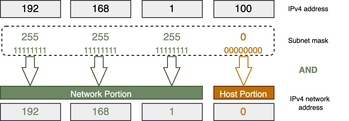
The subnet mask (also called the prefix length) separates the network portion from the host portion of the IPv4 address.
A subnet mask is 32 bits long. It has a group of 1s followed by a group of 0s. The 1s indicate the network portion of the IP address, and the 0s indicate the host portion.
How to Write a Subnet Mask
There are two ways to write a subnet mask:
Dotted Decimal Notation
We can use dotted decimal notation, just like for IPv4 addresses.
Example: 255.255.0.0
Slash Notation or Prefix Length
We can also use a slash notation, which shows the number of 1 bits in the mask.
Example:
- /16 (indicating 16 one bits)
- 172.18.0.0/16
Using the slash notation if more common nowadays.
Finding the IPv4 Network Address Using the Subnet Mask
Let’s say we have a host IPv4 address (192.168.1.100) and a subnet mask (255.255.255.0). How do we find the network address from the host address using the subnet mask?
In binary notation, we perform a bitwise AND operation between the host address and the subnet mask. For each bit position, if both the address and mask bits are 1, the result is 1. Otherwise, the result is 0. The result gives us the network address.
Making It Simpler
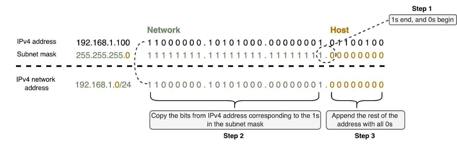
There is a shortcut way to find the network address using the subnet mask instead of doing bitwise AND operation. Let’s say we have a host IPv4 address (192.168.1.100) and the subnet mask (255.255.255.0). There are three steps:
- In the subnet mask, find where the 1s end and 0s begin.
- Copy the bits from the IPv4 address that correspond to the 1s in the subnet mask.
- Append 0s to the end to make a complete 32-bit IPv4 network address.
The image below shows these steps.
We need the subnet mask to determine which network the host belongs to. That’s why any IPv4 device has an IPv4 address and a subnet mask—the subnet mask tells the device its network.
Valid or Non-Valid Subnet Masks
It's easy to find the network and host portions when the subnet mask ends on an octet boundary, like /8 /16 or /24. But subnet masks don’t always fall on an octet boundary. To understand this, we need to know what makes a subnet mask valid or invalid.
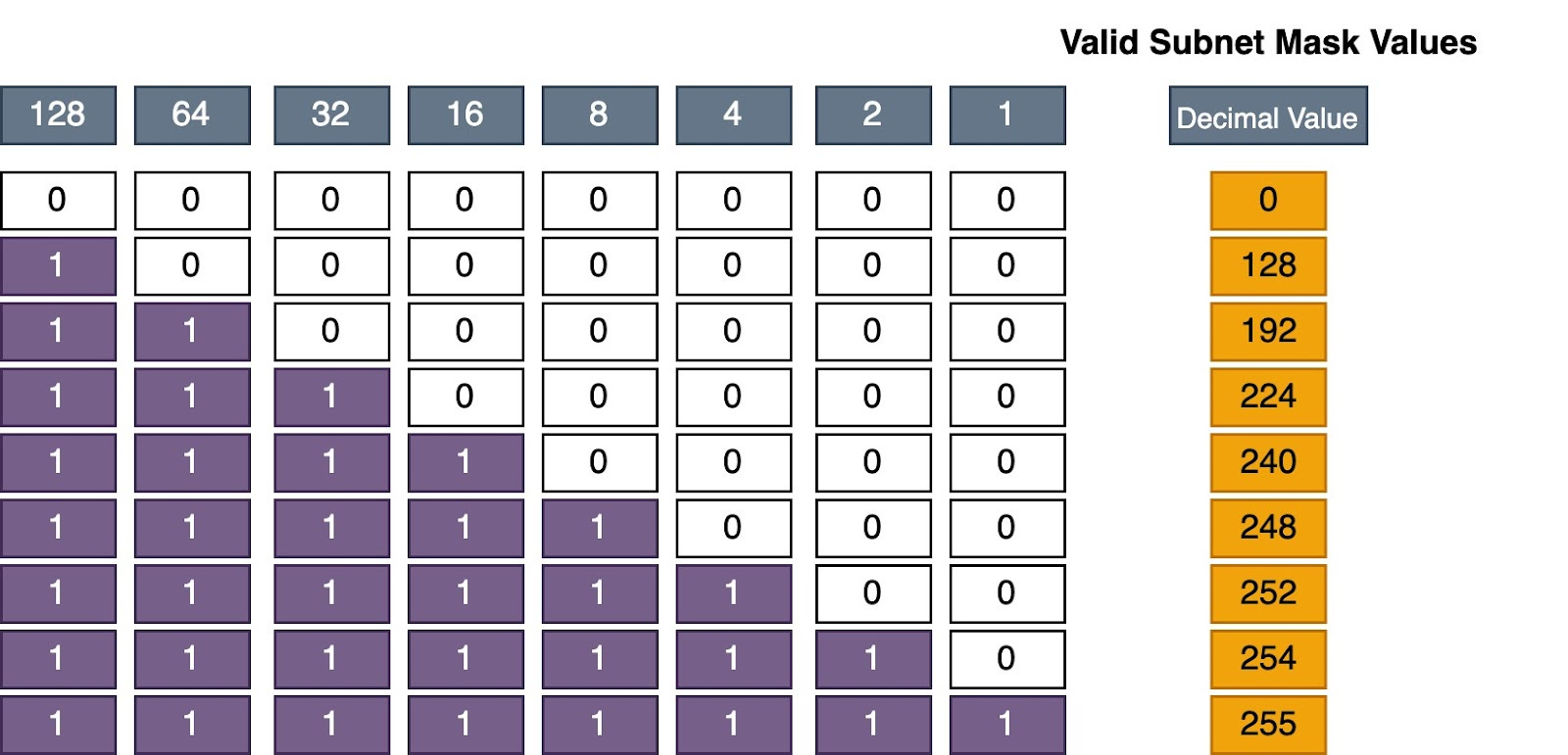
Remember, a subnet mask must have a group of 1s followed by a group of 0s. The image shows the only valid decimal values for a subnet mask.
The table below shows some valid and non-valid subnet masks:
[
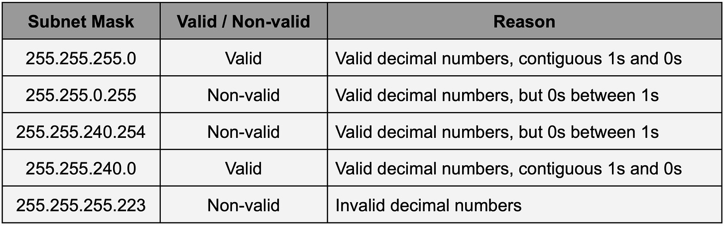
So sometimes we must convert a subnet mask to binary to see which network it belongs to, since it doesn't end on an octet boundary.
In summary, we need the subnet mask because the IPv4 address alone doesn't tell the device which network it belongs to. The subnet mask provides that information.
IPv4 Network, Broadcast, and Host Addresses
Network Address
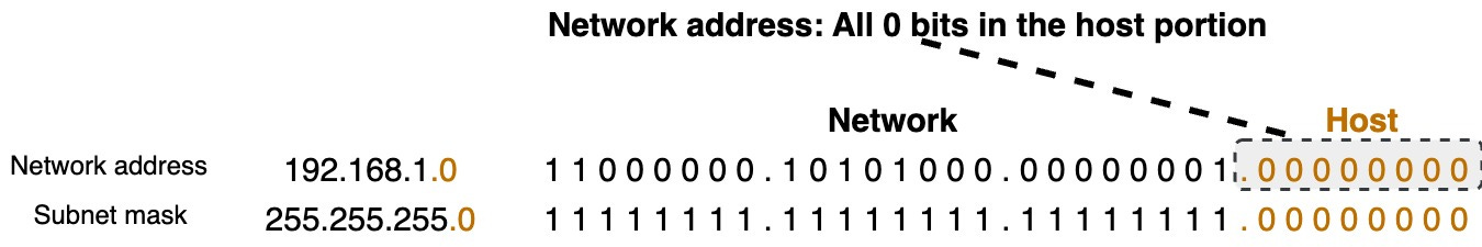
The network address always has all 0s in the host portion of the IP address. No device on the network can use the network address. This is why devices need a subnet mask to know the network and host portions of their address.
Broadcast Address
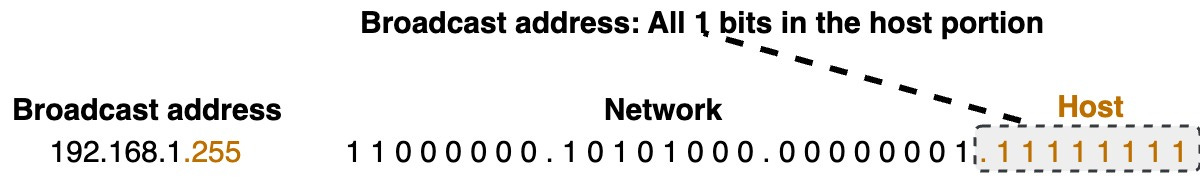
A broadcast address is a special IPv4 address used to send a message to all devices on the network. It has all 1s in the host portion.
Let’s take a look at an example of a broadcast address.
Just like the network address, no device is allowed to be assigned the broadcast address.
Host Address
A valid host address is any IPv4 address that is not the network address or the broadcast address. The host portion must contain at least one 0 bit and one 1 bit—it cannot be all 0s or all 1s. The host addresses are the usable addresses between the network address and broadcast address for devices on that network.
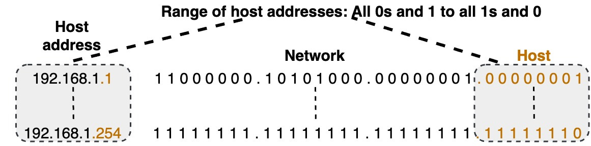
Going back to our 192.168.1.0/24 example, the network address is 192.168.1.0, and the broadcast is 192.168.1.255. The very first host address is 192.168.1.1 (00000001 in the host portion), and the last host is 192.168.1.254 (11111110 in the host portion). This range is what can be assigned to hosts.
All the host addresses will have the same network portion as the network address. Only the host part changes for each address.
💡1st Host address: It is common for the first host address (like 192.168.1.1) to be used as the router interface or default gateway address for that network.
Misperceptions
There are some common misperceptions about network and broadcast addresses:
- Network addresses don't always have to end in .0
- For example, with a /28 subnet mask, the network address ends in .64 (192.168.1.64). The network portion has some 0s and some 1s in the last octet, but the host portion is still all 0s, making it a valid network address
- Broadcast addresses don't always have to end in .255 - For the 192.168.1.64/28 network, the broadcast address is 192.168.1.79. The network portion has some 0s and 1s, so the broadcast doesn't end in .255.
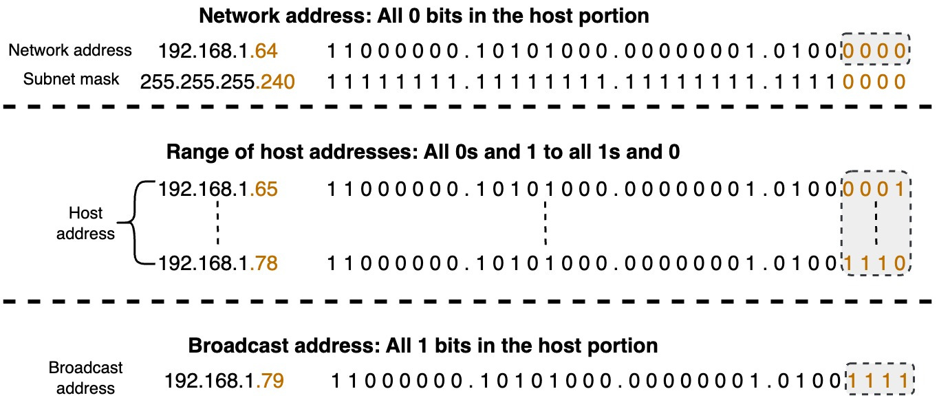

It can be tricky to visualize these address ranges just by looking at the decimal representations. Converting all the addresses to binary makes it much clearer to see where the network, broadcast, and host address ranges are for a given subnet mask.
Destination IPv4 Addresses: Unicast, Multicast, and Broadcast
Let’s talk about the different types of destination IPv4 addresses: unicast, multicast, and broadcast.
💡Note: We are focusing on destination addresses here, but it’s important to know that source IP addresses are always unicast addresses. This means the source of a packet can only come from one specific device.
Unicast Addresses
A unicast address is a network address assigned to a single network interface. It represents a unique endpoint on the network. When data is sent to a unicast address, it is intended for a specific device identified by that address. Unicast communication is one-to-one, where a single sender communicates with a single receiver.
Multicast Addresses
A multicast address represents a group of devices on the network. Unlike unicast addresses that represent a single device, multicast addresses are used for one-to-many communication. This means data sent to a multicast address is received by multiple devices that belong to a specific group.
Devices that want to receive multicast traffic can join a multicast group by using a special group address. When data is sent to a multicast address, it is delivered to all devices that have joined the corresponding multicast group. This allows efficient distribution of information to multiple recipients at the same time.
Multicast communication is often used for applications like multimedia streaming, video conferencing, and collaborative communication, where multiple devices need to receive the same data simultaneously. It reduces network traffic by delivering data only to those devices registered in the multicast group rather than broadcasting it to the entire network.
While multicast provides advantages and is widely deployed in specific sectors, it faces challenges with broader internet deployment. The large amount of state information routers need to maintain for multicast routing can make applications using many multicast groups unable to work properly. While multicast is commonly used in controlled environments and specific applications, its deployment on the public Internet has been limited
Broadcast Addresses
A broadcast address is a special type of network address used to send data to all devices on a specific network. In broadcast communication, the data is intended for every device within the designated network, allowing for one-to-all communication.
💡Note: With more efficient communication methods like unicast and multicast, routers do not forward destination IPv4 addresses by default. In IPv6, broadcast has been replaced by multicast and anycast communication.
IPv4 Subnet Mask and Packet Forwarding
Let’s talk about how IPv4 addresses and subnet masks help devices communicate on networks. Every device has an IPv4 address and a subnet mask. This information tells the device what network it belongs to. Each device on a network also has a default gateway address. If a device needs to send data to other devices outside its own network, it knows to send the data to the default gateway first.
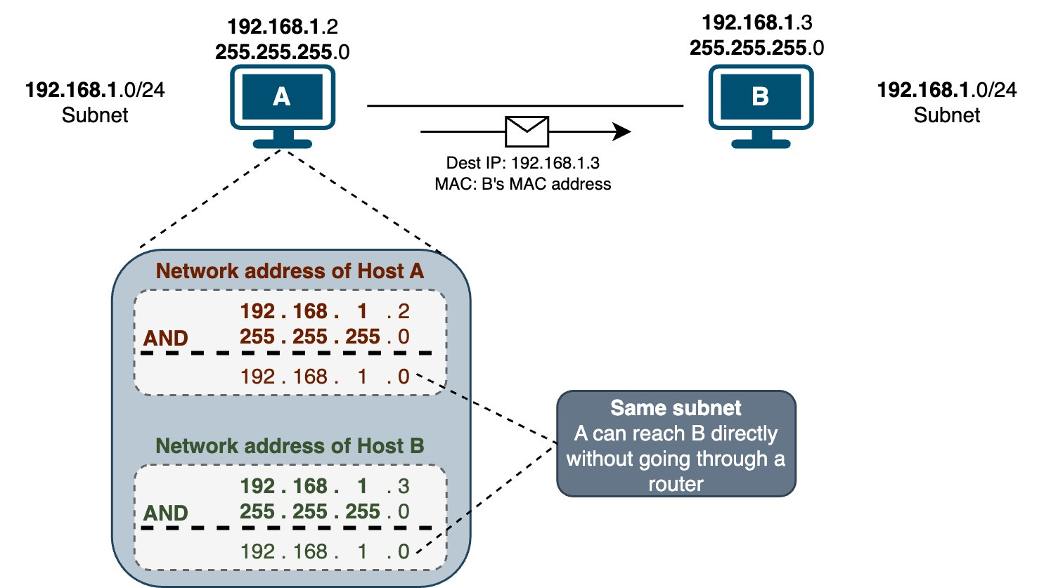
Sending Data to Devices on the Same Network
IPv4 devices can only communicate directly with other devices on the same subnet. Let’s look at an example to understand this better. Suppose Host A needs to send data to Host B at address 192.168.1.3. How does A know if B is on its network? Host A follows these steps:
- Host A knows that it is on the 192.168.1.0/24 subnet (by performing bitwise AND operation on its IP address and subnet mask)
- Host A knows that Host B (192.168.1.3) is also on its same subnet (by performing a bitwise AND operation on Host B’s IP address and Host A’s subnet mask)
Since Hosts A and B have the same network address, they are on the same network. Host A can now send the data directly to Host B’s MAC address. If Host A doesn't know Host B’s MAC address yet, it will send out an ARP request to get the MAC address from Host B. Once Host A has Host B’s MAC address, it can send the data.
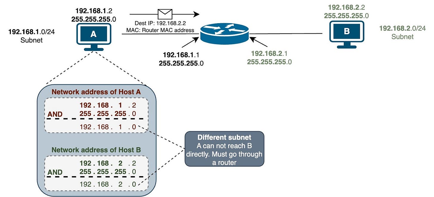
Sending Data to Devices on a Different Network
Now let's look at another example where Host A needs to send data to Host C at 192.168.20.12 on a different network. Here are the steps performed by Host A:
- Host A knows it is on the 192.168.10.0 /24 subnet
- Host A knows Host C (192.168.20.12) is on a different subnet
Since Host C is on a different network, Host A cannot send data directly to Host C. Host A needs to send the data to its default gateway instead. The router will then forward the data to Host C's network.
[
Private and Public IPv4 Addresses
We are running out of IPv4 addresses (only 4.29 billion). We needed some quick fixes and a long-term solution. The quick fixes were:
- NAT (network address translation)
- Private address space
- CIDR (classless inter-domain routing)
IPv6 is the long-term fix, and it's happening now.
Private IP Addresses
Private addresses and NAT have kept IPv4 going longer than it should have. RFC 1918 defines the private IPv4 address space.
- These addresses are for private networks only, not the Internet.
- They are used for internal communication within a home or business network.
- The private IP address ranges are:
- 10.0.0.0 to 10.255.255.255
- 172.16.0.0 to 172.31.255.255
- 192.168.0.0 to 192.168.255.255
- Devices within a private network can use these addresses without any conflicts.
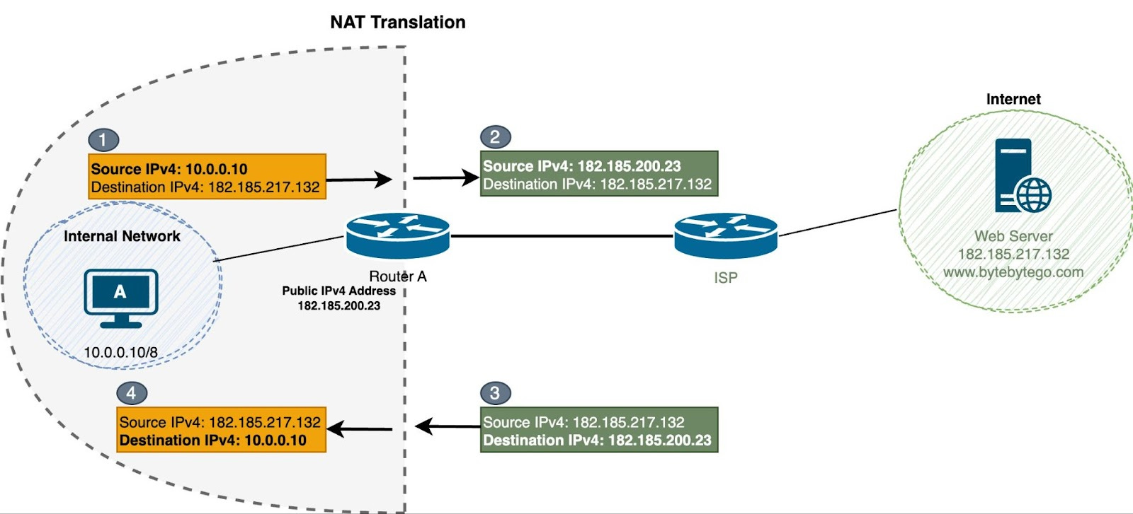
NAT for IPv4
Any device in a network can use the private IPv4 addresses. But they don't work on the Internet. Service providers will drop packets with private source or destination addresses.
So, how do devices inside a network get on the Internet? They use NAT (network address translation). NAT translates private IPv4 addresses to a public routable IPv4 address. The NAT software is typically installed on a router.
There are three ways to do NAT translation:
Static NAT: This is when one private IP address gets mapped to one public IP address. The mapping stays the same. It is used when we are outside the network and want to reach a device or server inside that has a private address.
Dynamic NAT: This lets multiple private IP addresses get mapped to a pool of public IP addresses. The mapping changes and is only temporary. The public IP addresses come from the pool as needed. When a session ends, the public IP address goes back to the pool to be used again.
The problem is it's a one-to-one translation. So if we have 5 public IPv4 addresses, we can only NAT a max of 5 internal devices. That's why it's not used much these days.
PAT (Port Address Translation) or NAT Overload: This is a variation of dynamic NAT. It maps multiple private IP addresses to a single public IP address using UDP or TCP port numbers (which are 16-bit). In theory, we could have over 65,536 translations for internal devices. This means hundreds or even thousands of private RFC 1918 IPv4 addresses can be translated to just one public IPv4 address. This is what's really kept IPv4 from running out over the years.
Public IP Addresses
Public IP addresses work on the Internet and are unique worldwide. IANA (Internet Assigned Numbers Authority) is in charge of assigning these public IP addresses. They're used for communication between devices on the Internet.
In a typical network setup, a router sits between the private network and the Internet. When devices in the private network want to access the Internet, the router uses NAT to map multiple private IP addresses to a single public IP address. This helps save public IP addresses and also adds some security by hiding what the internal network looks like.
IP Address Allocation
Who assigns IP addresses (IPv4 and IPv6)? The Internet Assigned Numbers Authority (IANA) is responsible for allocating IP address space to groups called Regional Internet Registries (RIRs). Five RIRs exist in different regions of the world:
- AfriNIC (African Network Information Centre) - Africa Region
- APNIC (Asia Pacific Network Information Centre) - Asia/Pacific Region
- ARIN (American Registry for Internet Numbers) - North America Region
- LACNIC (Regional Latin-American and Caribbean IP Address Registry) - Latin America and some Caribbean Islands
- RIPE NCC (Reseaux IP Europeans) - Europe, Middle East, and Central Asia
Larger companies and universities can obtain their IP address space directly from their regional internet registry (RIR). This is also known as provider independent address space because they're not going through an Internet Service Provider (ISP) to get their address space. Most other organizations will go through their ISP to get address space.
Legacy Classful IPv4 Addressing
Back in the day, IPv4 addresses were assigned in a classful manner. It was an outdated system specified by RFC 791, which grouped unicast addresses into three sizes.
- Class A, B, and C addresses (for users): User or network addresses ranged from 0.0.0.0 to 223.255.255.255.
- Multicast addresses: Still used today, ranging from 224.0.0.0 to 239.255.255.255.
- Experimental addresses: Never used, ranging from 240.0.0.0 to 255.255.255.254.
Classes A, B, and C each had a specific subnet mask. Class A had 255.0.0.0 or /8 subnet mask, which means the first 8 bits were the network portion, and the last 24 bits were the host portion. The image below shows the subnet masks of Class B and C.
[
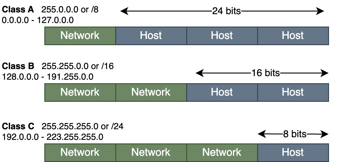
This classful addressing scheme was quite inefficient. The available address space was limited, and the allocation was inflexible. Class A addresses could accommodate 16 million hosts, Class B addresses allowed for 65,000 hosts, and Class C addresses supported only 254 hosts.
In contrast, today, we use Classless Inter-Domain Routing (CIDR). Compared to the traditional class-based system, CIDR offers a more flexible approach to IP address allocation. In CIDR notation, an IP address is followed by a forward slash and a number, such as 192.168.1.0/24. The number after the slash indicates the number of bits used for the network portion of the address.
For example, 192.168.1.0/24. The "/24" indicates that the first 24 bits represent the network, and the remaining 8 bits represent individual host addresses within that network.
💡Note: CIDR simplifies routing table management by aggregating IP addresses into blocks and advertising those blocks as a single route. This method reduces the size of routing tables on Internet backbone routers. It enhances the efficiency of IP address allocation as the Internet continues to grow and the available address pool becomes more limited.